The backfill is horizontal. MSE Wall Section with Type 1-AT Connection PDF DWG.
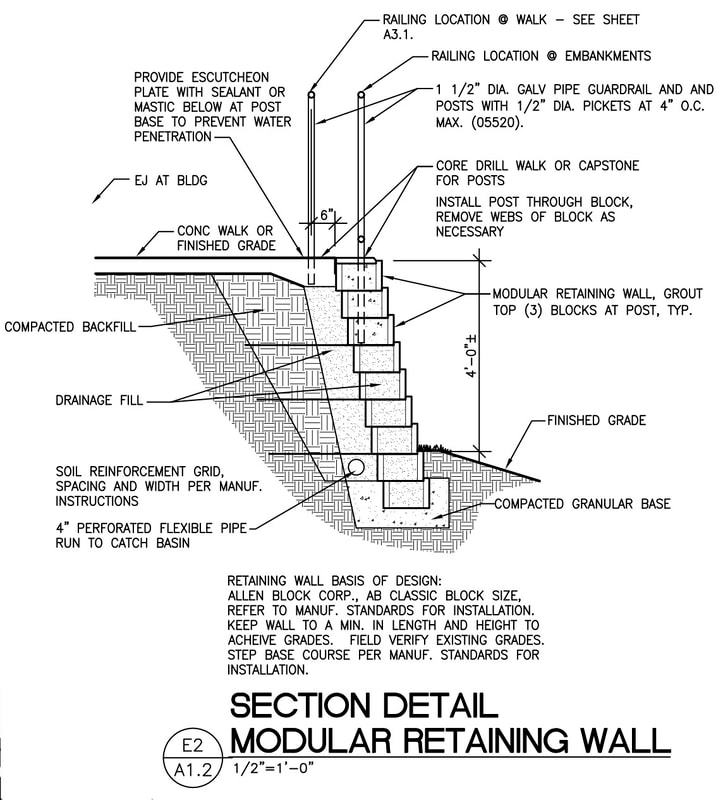
Modular Masonry Retaining Wall Architekwiki
4 Batter Drainage Hole Toe Cantilever Retaining wall.
. Anchor Block Retaining Wall PDF DWG. Allan Block Terraced Wall Detail Author. As a rule of thumb this method works and will give a factor of.
SD Drawing Number Description View SD Drawing as PDF Download Microstation DGN as ZIP. Gravity Retaining Walls Gravity retaining walls are a basic design and rely on the mass of the wall to retain the earth behind. Take the co-efficient of friction between concrete and soil as 06.
Note rockfill surcharge on crest of wall The toe wall provides passive toe restraint so the wall did not have to be excavated as deeply against the existing road. Retaining wall Design Design example-1 Design a cantilever retaining wall T type to retain earth for a height of 4m. Anchor Block Section PDF DWG.
Ad Find The Best Retaining Wall Construction In Your Neighborhood. Anchor Block Waler Beam Detail PDF DWG. A very simple method to design a gravity retaining wall is to use the base width x 2 to calculate the height.
Forces on Retaining Walls 6. Subdrainage behind walls allows their design. CIP Coping Detail PDF.
Fc 3000 psi fy 60 ksi Natural Soil Development of Structural Design Equations. 32 32 13 - Cast-in-Place Concrete Retaining Walls. Vertical Tie-Down System with Earth Anchors PDF DWG.
32 32 19 - Unit Masonry Retaining Walls. DESIGN AND DETAILING OF RETAINING WALLS. 32 31 29 - Wood Fences and Gates.
In this example the structural design of the three retaining wall components is performed by hand. Verify that the wall system selected will conform to the common to the wall system selected. Type 1-AT Connection PDF DWG.
Retaining Wall Reinforced Concrete Cantilever 1 of 5 SD 701-1. Allan Block Terraced Wall Detail Created Date. DESIGN AND DETAILING OF RETAINING WALLS For class held from 2nd April 07 Dr.
Note tar joint between floor slab and stem wall. Retaining walls are usually built to hold back soil mass. The following drawings are for general information and use.
Retaining walls Example 316 Design of a cantilever retaining wall BS 8 110 The cantilever retaining wall shown below is backÞlled with granular material having a unit weight of 19 kNm 3 and an internal angle of friction of 30. STANDARD GRAVITY-TYPE RETAINING WALLS. Calculate the horizontal pressure on the wall.
Hybrid Combination Walls GravityReinforced PrecastCast In Place All Hybrid. Crushed rock-filled gabion retaining wall supporting an ancient sinkhole feature along the eastbound lanes of Interstate 44 just east of Vichy Road in Rolla. Two equations are developed.
3 Gravity retaining wall GL1 GL2 Retaining walls are usually built to hold back soil mass. Standard I Straight 21 Detail PDF. Sketch the drawings and detail as per the requirements.
Browse Profiles On Houzz. The wall in figure 1 is 800mm wide and 1600mm high. They are not to be relied upon for any specific project.
Retaining walls designed using code tabulated values shall meet the conditions cited below. Connect With Top-Rated Local Professionals Ready To Complete Your Project on Houzz. Bridge Railing Standard Drawings.
Design retaining wall for a live load surcharge of insert behind wall as shown. FOR UP TO 2 OF FILL. Design Procedure Overview 3.
32 31 26 - Wire Fences and Gates. The density of soil is 18kNm3. Earthquake Seismic Design 7.
Concrete deadman driven into the ground or anchored into the earth with sufficient resistance. Safe bearing capacity of soil is 200 kNm2. Assume a breath for the base is 075 of the wall height.
However retaining wallscanalsobeconstructed for aesthetic landscaping purposes. Assuming that the allowable bearing pressure of the soil is 120 kNm 2 the. 32 32 29 - Timber Retaining Walls.
Revised Miscellaneous and Retaining Wall Standard Drawings. The preliminary thickness for the wall and base section can be assumed. Each file also is available for download in AutoCAD dwg or dxf or Adobe Acrobat pdf file format.
Design for retaining wall to provide for finished grade sloped on this sheet. Retaining Wall Design 10 Editionth A Design Guide for Earth Retaining Structures Contents at a glance. Building Codes and Retaining Walls 5.
Nataraja Professor Civil Engineering Department Sri Jayachamarajendra Collge of Engineering Mysore-5a70 006 Phone. Country ManorStonegate Detail PDF. New Bridge Railing Guide Drawing.
Types of Retaining Walls-Gravity walls - Pre-cast crib walls - Gabion walls - Reinforced concrete walls - Sheet pile walls - MS walls mechanically stabilized - Slurry and Secant Walls - Soil nailing L. 32 32 16 - Precast Concrete Retaining Walls. New and Revised Retaining Wall Standard Drawings.
51 SINGLE SLOPE CONCRETE BARRIER WALL. In general they are used to hold back or support soil banks and water or to maintain difference in the elevation of the ground surface on each of wall sides. Then considering all forces check stability against overturning and the vertical pressure under the base of the.
Vertical Tie-Down System PDF DWG. Click on the drawing to view or print a larger image. Soil Mechanics Simplified 4.
Allan Block Retaining Walls Subject. Click image to open PDF DRAWING. To download a detail click on the desired file format dwg dxf or pdf and save the file to your computer.
Retaining walls are structure used to retain soil rock or other materials in a vertical condition. The retaining wall is to be designed using the elevations given required alignments and details. Soil Bearing and Stability 8.
Types of Retaining Walls Tieback Wall Tieback is a horizontal wire or rod or a helical anchor use to reinforce retaining wall for stability One end of the tieback is secured to the wall while the other end is anchored to a stable structure ie. Retaining Wall Reinforced Concrete Cantilever 2 of 5 SD 701-2. Fill materials behind retaining walls shall be fully drained of water and other fluids by means of sub-drain weep holes andor other approved method at least equivalent to the attached detail.
32 31 23 - Plastic Fences and Gates. Retaining Wall Drainage This detail comes from a 1934 publication showing concrete drain tile pipe should be placed at the base of the basement wall footing not the base of the stem wall. RETAINING WALL BACK SOIL.
CIP Traffic Barrier Detail PDF. Up to 24 cash back Design procedure cantilever retaining wall. Revised Culvert and Drainage Standard Drawings.
DESIGN AND ANALYSIS OF RETAINING WALLS 81 INTRODUCTION Retaining walls are structures used to provide stability for earth or other materials at their natural slopes. CE 437537 Spring 2011 Retaining Wall Design Example 1 8 Design a reinforced concrete retaining wall for the following conditions. Download Retaining Walls Reinforced Concrete Cantilever All SD 701 All.

Building Guidelines Drawings Section A General Construction Principles Figures 11 16 Retaining Wall Wall Retaining Wall Drainage
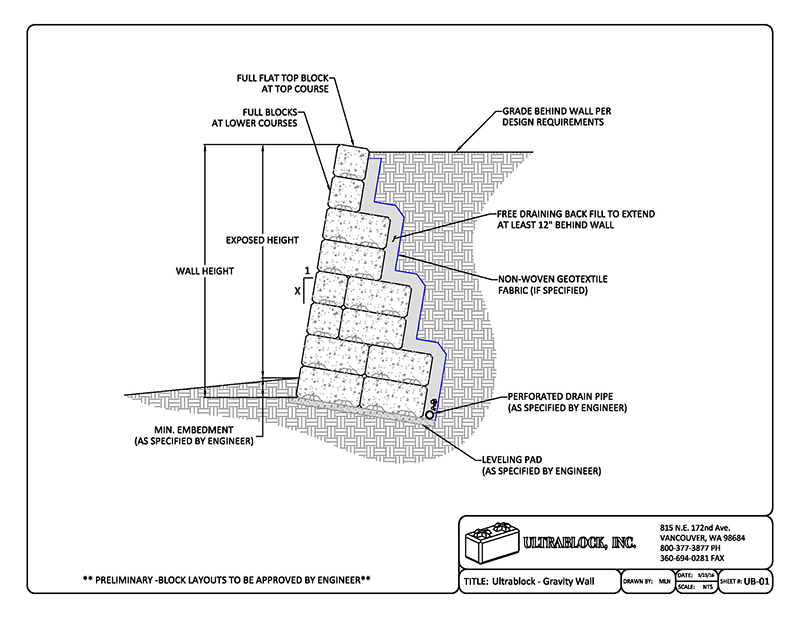
Ultrablock Retaining Wall Drawings
2

Reinforced Concrete Retaining Walls Bundled Drawing Details Concrete Retaining Walls Retaining Wall Construction Reinforced Concrete

Retaining Wall 2 0 M Pdf

Typical Retaining Wall Construction
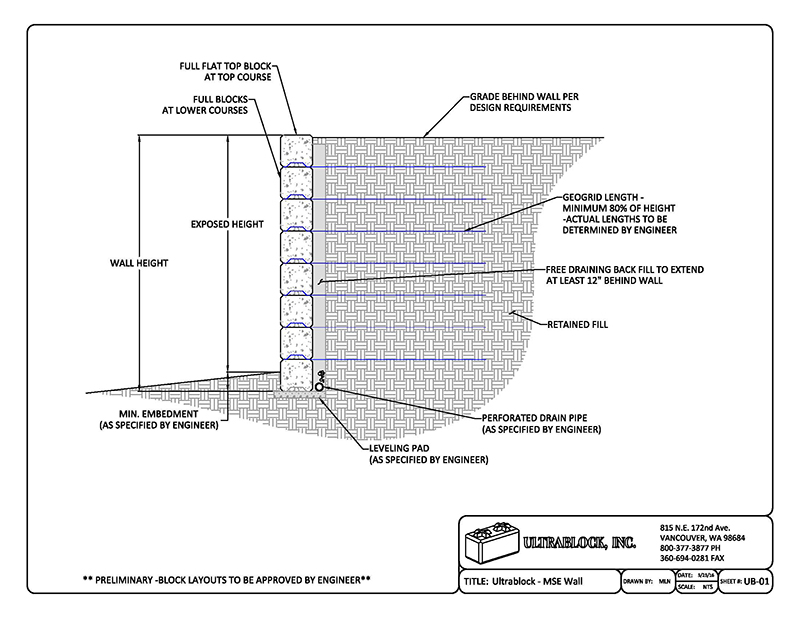
Ultrablock Retaining Wall Drawings

Allan Block Retaining Wall Design Details
0 comments
Post a Comment